|
Untitled Document
|
|
 |
| |
 |
| |
|
| |
 |
| |
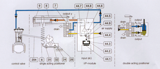
The positioner works according to the
force-balance principle. The input signal,
coming from the control equipment, acts
on a diaphragm chamber. The force produced
ing such a way is constanthly compared to
the feedback force produced by the stroke
scanning lever (204), cam-disc (24) and
spring (6). Accrding to the control divergence
the valve spindle is forced into the correct
position by higher or lower output pressure
on the actuator, until the control diver-gence
between input force and reset force has
become zero.
Looking at the I/P module in the above acheme,
the input current I flows through a fixed
coil (44.1). There by a soft magnetic system
(44.2) ist magnetized. The flux lines of
this system being exposed at a gap (44.3)
apply a force proportional to the input
current to a small magnet (44.4) made of
highly coercive alloy. Together with the
flapper (44.5) this small magnet forms the
moving parts of the system.
The flaper more or less covers a nozzle
(44.6), the air flowing from the nozzle
forming a restoring force balanced by the
force applied to the magnet. The nozzle
is supplied with air through a fix orifice
(44.7) by the output of a controlling unit
(44.8) influenced by the pressure change
before the nozzle. Hence a well linear corespondance
of clectric input and pneumatic output signal
is achieved.
Zero adjustment is made in the pneumatic
part of the unit by adjusting the screw
(31), the rough range adjustment is performed
at the stroke lever (204) and the final
adjustment at the adjusting screw(32). The
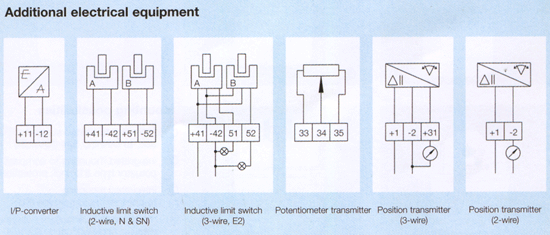
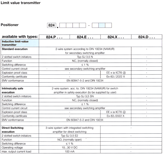
adjustment of the limit switches is made
possible by adjustable control flappers
(damped and undamped).
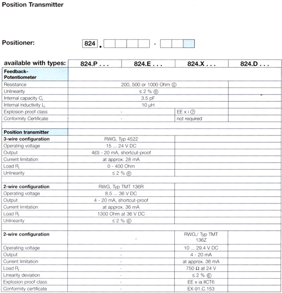
The zero and range adjustment of the electronic
position transmitter ensue at the marked
adjusting screws (0/100%) of the transmitting
module. |
|
| |
 |
| |
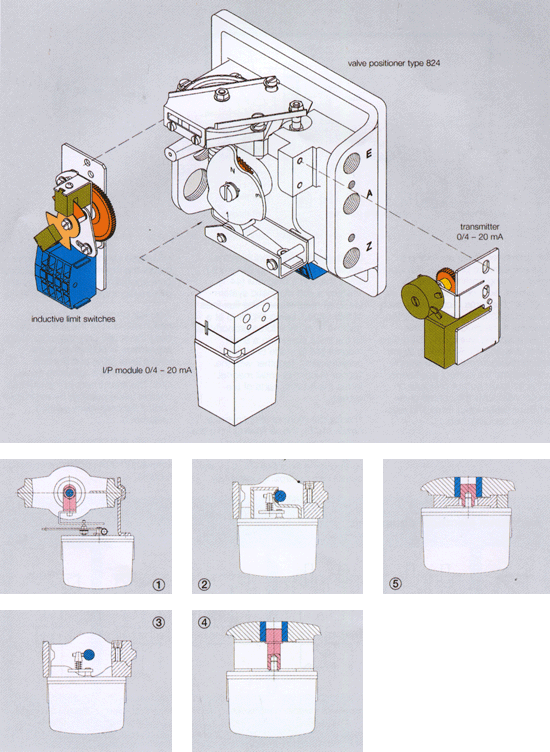 |
| Mounting possibilities |
| ① |
mounting to casted support acc. to DIN/IEC
534 (NAMUR) |
| ② |
integrated mounting to compact actuator
type 812 incl. protection hood |
| ③ |
integrated mounting to compact actuator
type 812 |
| ④ |
mounting to quarter-turn actuator, rotating
angle 90°, acc. VDI/VDE |
| ⑤ |
integrated mounting to ARCATORQUE |
|
| |
 |
| |
 |
|
| |
 |
| ② |
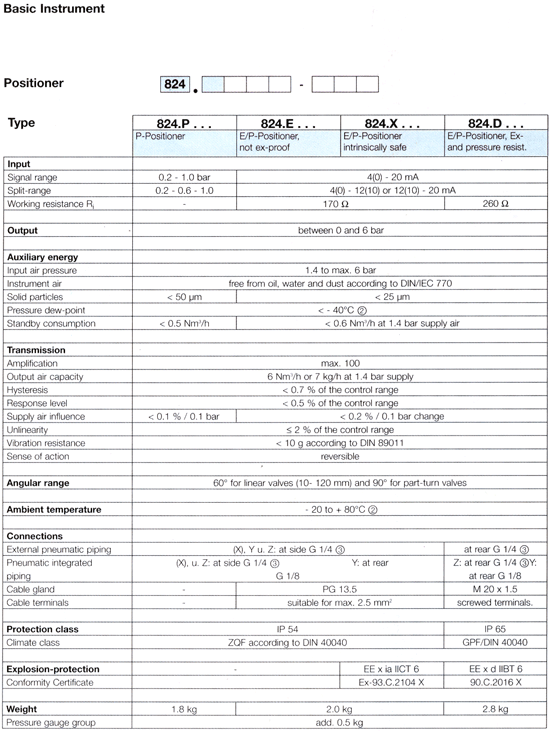
Special execution up to -40℃ (pressure dew-point
< -50℃) |
| ③ |
Special execution NPT 1/4" |
| ④ |
Only in combination with corresponding ex-proof
switching amplifier |
| ⑤ |
Zero-point of and range must be adjusted
at the receiving instrument. |
| ⑥ |
A deviation of up to 5% is possible, depending
the installation mode the positioner and/or
the stroke-range |
| ⑦ |
Passiv element; a conformity certificate
is, therefore, not required, but the allowale
external inductivity (La) and capacity (Ca)
must both be larger than Li and Ci of the
potentiometer. |
|
| |
 |
| |
|
|
| |
|
