 |
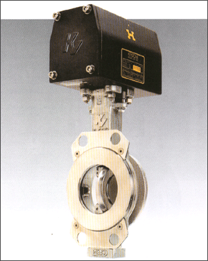
High Performance
Butterfly Valve
Sizes 2(50A) 36 Inch(900A)
ANSI Class 150 and 300
JIS 10K and 20K |
|
| |
Features
and Benefits
● Integrally cast mounting pad procides
direct mounting of Keystone actuators
● Rocker-shaped gland bridge compensates
for uneven adjustment of gland nuts.
● Extended neck allows for two inches of
pipeline insulation.
● Flattende body bore at stem journal ports
positions stem bearings near disc, providing
maximun stem support.
● Disc taper pins are tangentially positioned
half in disc and falf in stem, placing them
in compression rather than shear, which
eliminates potential for failure.
● Integrally cast disc position stop perfectly
locates the disc in seat, achieving maximun
seat and seal life.
● Uninterrupted flange face retaining ring
allows use of standard spiral wund gaskets
and provides unidirectional dead-end service
as standard. Bi-directoinal dead-end service
is available.
● K-Lok polymer, elastomer, and fire-safe
seats provide bi-directional, drop-tight
closure in vacuum and throughout all pressure
ranges, as well as at full rated differential
pressure. A variety of materials allows
optimum seat life in all applications. |
| |
| Recommended
Standard and Specifications |
| |
| ANSI- |
B16.34
B31.1
B16.5
B31.3 |
Steel valves
Power piping
Steel pipe flanges and flange fittings
Chemical Plant and petroleum refinery
piping |
| MSS- |
SP-6
SP-25
SP-55
SP-61
SP-67
SP-68 |
Standard finishes for pipe flanges
Standard marking systems for valves
Quality standard for steel casting
Pressure testing of steel valve
Butterfly valves
High pressure offset seat butterfly
valves |
| API- |
609
607
598 |
Butterfly valves
Fire test soft seated quarter-turn valves
Valve inspection and test |
| BS- |
5146
4504 |
Inspection and test steel valves for
the petroieum, petrochemical and allied
industries
Flanges and bolting for pipes, valves
and fittings |
| DIN- |
3230 |
Technical conditions of delivery for
valves |
| ISO- |
5752
2084 |
Metal valves for use in flanged pipe
systems
Pipeline flanges for general use |
| JIS- |
2220 |
Steel welding pipe flanges |
|
| |
 |
| |
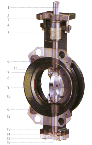
| Materials |
| |
| No |
Part |
Material |
Material Standards |
| 1 |
Stem |
17-4PH SS |
ASTM A564 H1075 or H1100 |
| 2 |
Body |
Carbon Steel
Stainless Steel |
ASTM A216 WCB |
| 3 |
Gland Bridge |
17-4PH SS |
ASTM A351 CF8M or CF8 |
| 4 |
Packing Gland |
316 Stainless Steel |
|
| 5 |
Stem Packing |
RTEF
Graphite |
|
| 6 |
Stem Bearing |
RTEF fiberglass epoxy
316SS Nitrite |
|
| 7 |
Body Gasket |
Non-asbestos
Graphite |
|
| 8 |
Disc |
Stainless Steel
Al-Bronze |
ASTMA351 CF8M or CF8
ASTM B148-952 |
| 9 |
Seat |
Polymer
Elastomer
Metal
Fire-safe |
PTFE or RTFE
Viton, Buna-N(NBR), EPDM
316 Stainless Steel
RTFE/316 Stainless Steel |
| 10 |
Seat Backing Ring |
Polyester or Phenolics
Stainless Steel |
|
| 11 |
Seat Retainer Ring |
Carbon Steel
Stainless Steel |
ASTM A36
ASTM A351 CF8M/A276-316 |
| 12 |
Flange Locator Plate |
Carbon Steel zinc plate
Stainless Steel |
|
| 13 |
Disc Locator |
316SS |
|
| 14 |
Bottom Cover Gasket |
Non-Asbestos
Graphite |
|
| 15 |
Bottom Cover Plate |
316SS |
ASTM A351 CF8M/A276-316 |
| 16 |
Thrust Washer |
Stainless Steel/RTFE
Stainless Steel Nitrite |
|
|
| |
|
| |
Principles
of Operation
Double
Offset Disc/Stem
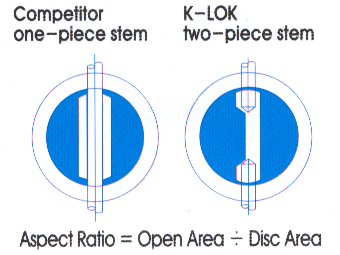
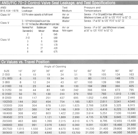
K-LOK's unique two-piece stem and double-offset
disc/stem design allows for high cycling and
creates a lower disc profile with increased
capacity and a rangeability of 33:1
In addition to increasing the flow area across
the disc, this design minimizes wear points
between seat and disc.
The first offset is achieved by locating the
stems downstream of the center-line of the
seat. This allows for a totally unobstructed
360° sealing surface.
The second offset locates the stems off-center
of the vertical axis of the seat.
The combination of these two offsets creates
a camming effect as the disc swings into and
out of the seat. The disc swings into and
out of the seat. The disc lifts quickly out
of the seat in the first few degrees of travel
and does not contact the seat again until
it is nearly closed.
There are no wear points betwoon the seat
and disc, while operating torques are reduced
and seat life is extended.
Two-piece
Stem vs. One-piece Stem
K-LOK's disc geometry maximizes flow capacity
by increasing the available flow area through
the valve. This increase in disc effciency
results in a higher valve Cv. |
| |
 |
| |
Fire Safe Valve
API607 4th Edition Approved by Third
Parth Witness
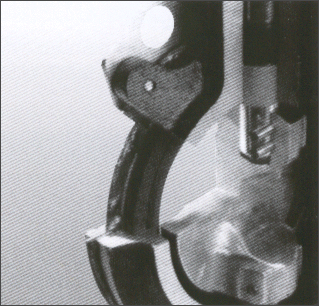
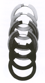
The K-LOK fire-safe design uses a stainless
steel or MONEL allry seat of convoluted shape
that mates with an RTFE member, Inthe full-closed
position, the K-LOK provides continuous tow-plane
contact between the disc and both metal and
RTFE seats. The fire-safe seat utilizes wire
windings to provide the circumferential stiffness
necessary to maintain interference between
disc and seat. |
| |
Fire-Safe Seat
|
| |
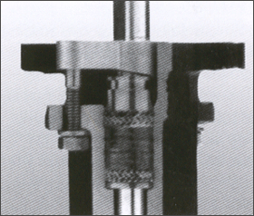
Fire-Safe Packing
K-LOK fire-safe packing is composed of three
ring of preformed graphite between one ring
of woven graphite rope at the top and bottom
This arrangement creates a superior, high
temperature seal against the outer wall of
the packing box and around the rotating stem.
Fire-Safe Packing
|
| |
 |
| |
 |
| |
| Seat Design |
| |
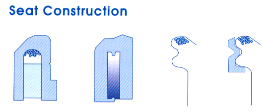
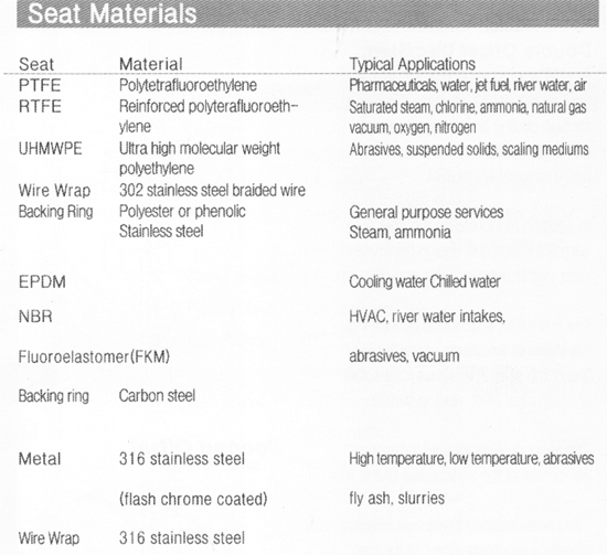
The K-LOK seat is a true interference
seat design and dose not rely on line
pressure to assist in sealing. All seats
seal drop-tight bi-directionally at
low pressure as well as high pressure.
Polymer(PTFE, RTFE and UHMWPE) seats
incrporate a stainless steel braided
wire winding, enclosed in a U-shape
envelope to provide seating energy and
memory. This wire winding allows axial
flexibility in both directions of flow.
The winding also allows radial flexibility
when the disc is not fully closed, reducing
seat/disc interference, seat wear and
stem torque. When the disc closes, it
provides circumferential stiffness and
assures the required disc/seat seals
tight.
Elastomer seats are molded around a
stack of V-shaped steel rings that provide
the same stability, support and flexure
as the wire windings in polymer seat. |
 |
|
Metal seats employ a stainless steel or MONEL
ring of convoluted shape, reinforced by stinless
steel wire windings. The thin, convoluted
shape allows for expansion and contraction
from thermal cycling. Long life is assured
by flash coating the seat with chrome. |
| |
 |
| |
| Actuator |
Figure |
Remark |
| Handle |
F401 |
Lever lock |
| Gear |
F420 & F500 |
|
| Pneumatic |
F79X |
An extended travel
design |
| Gear & Pneumatic |
F453 + F79X |
Declutchable gear unit provides manual
override for the Keystone pneumatic
atuator. |
| Electric |
F777 |
|
|
| |
Common Available
Trims
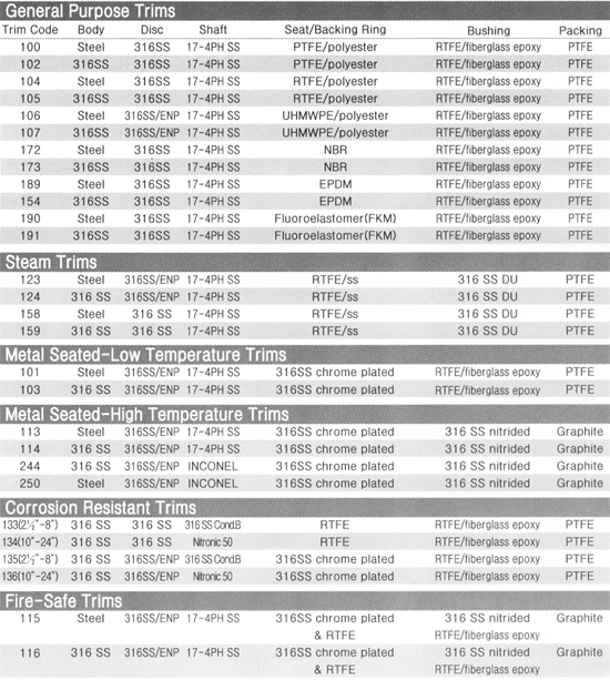
To order a K-LOK, specify the valve size,
the specific application trim code. The most
common codes, together with the materials
of construction, are listed below. |
| |
 |
| |
 |
| |
Seating and
Un-seating Torque
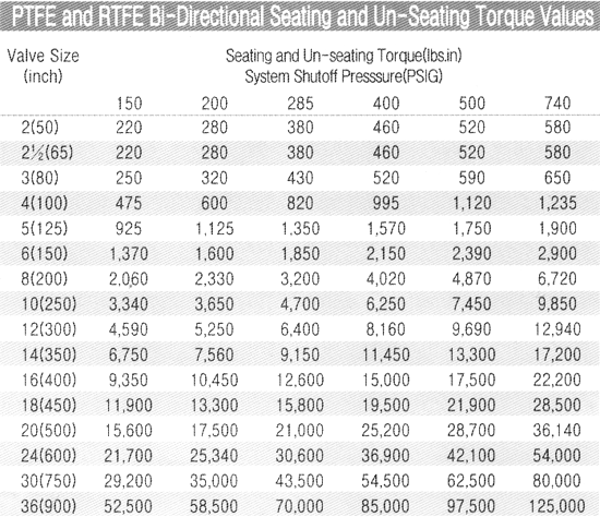
Seating and un-seating torques are a function
of the size of the valve and the shutoff pressure
of the system.
Specific torque ratings can be found in the
seating/Un-Seating chart at the intersection
of the 'size' row and the 'shutoff pressure'
column.
Torques listed are for PTFE and RTFE seated
valves. For different seat materials specific
multipliters are to be used as stated.
All torques listed are for normal/service
conditions(I.e.operating frequency is a minimum
of once per month:disc corrosion is expected
to be mild or minor, the media is a clean
gas, liquid or steam, and is non-abrasive)
and chemical affects upon the seat are minor. |
| |
 |
| |
 |
