 |
Technical
data
Pressure(bar) :10
Temperature(℃) : -40 +120
Sizes(mm) : 700~2000
Flange
accommodation : PN 6/10
Sizes up to 2800 available on request.
General
application
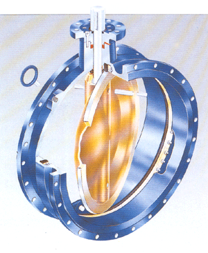
The Figure 56 design offsets an excellent,
low cost solution for municipal water
treatment, desalination, power generation
and industrial applications. |
|
| |
Features
and Benefits
● Designed basically for the waterworks
industry, Fig.56 in full compliance with
ISO 5752, ISO-13 with actuator flange acc.
ISO 5211.
● It is a cast double flanged butterfly
valve, which can be driled acc. various
flange standards (JIS, BS, DIN, ANSI) and
also provide dead-end service capability
with down strearm piping removed.
● Body and disc protective coatings are
available for sea water or corrosive sevices
as for external pro tection.
● The low profile one-piece seat provides
an un-interrupted 360° seal and is fully
adjustable to tightness regardless of changing
piping stresses. No bonding to the body
is required. The seat is replaceable without
special tooling, dismanting or removing
the valve from the line.
● The special seat and disc edge contours
reduce seating torque, provide better shut-off
and longer service life.
● A stainless steel disc edge resists against
corrosion and avoids encrust build-up for
consistent sealing.
● Full diameter stub shafts remain dry and
provide a positive disc control
● High strength stub shafts have full 1
1/2diam. penetration into disc-hubs with
close tolerance-fit. |
| |
 |
| |
| Part Name |
| |
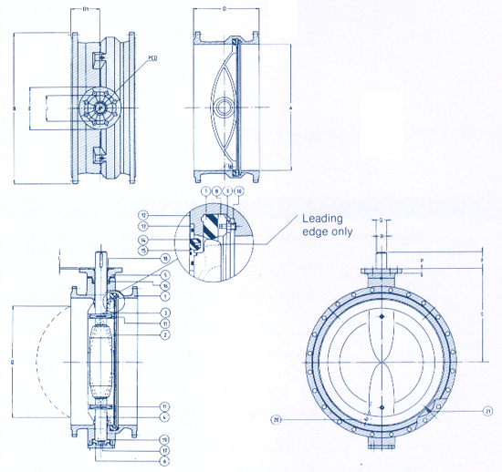
1. Body 2. Disc 3. Upper shaft
4. Lower shaft 5. Actuator flange
6. Cover Plate 7. Seat
8. Seat retaining segment 9. Seat adjusting
nut 10. Seat retaining screw
11. Disc pin
12. Bearing 13. Sleeve body/shaft
14. Shaft seat 15. Sleeve disc/shaft
16. Seal ring
17. Axial positioning ring 18. Dirtscraper
19. Axial bearing (reinf. PTFE)
20. Travel stop
21. Supporting lug (4x) |
| |
| Valve dimensions
in mm |
| |
| Size |
A |
B1 |
C |
D2 |
D1 |
Q |
Shaft
G3 |
Actuator flange
acc. ISO 5211 |
Mass
(kg) |
| 700 |
700 |
895 |
623 |
292 |
86 |
658 |
50/60/70 |
F-14/F-16 |
470 |
| 750 |
750 |
965 |
598 |
318 |
105 |
703 |
60/70/80 |
F-16/F-25 |
530 |
| 800 |
800 |
1015 |
623A |
318 |
99 |
757 |
60/70/80 |
F-16/F-25 |
620 |
| 900 |
900 |
1115 |
673A |
330 |
97 |
859 |
60/70/80/90 |
F-16/F-25 |
750 |
| 1000 |
1000 |
1230 |
730 |
410 |
159 |
934 |
70/80/90/100 |
F-25/F-30 |
1030 |
| 1100 |
1100 |
1340 |
798 |
470 |
197 |
1012 |
80/90/100/120 |
F-25/F-30 |
1270 |
| 1200 |
1200 |
1455 |
848 |
470 |
185 |
1129 |
80/90/100/120 |
F-30/F-35 |
1520 |
| 1300 |
1300 |
1575 |
918 |
530 |
212 |
1216 |
90/100/120/140 |
F-30/F-35 |
1875 |
| 1400 |
1400 |
1675 |
968 |
530 |
219 |
1319 |
90/100/120/140 |
F-30/F-35 |
2240 |
| 1500 |
1500 |
1785 |
1038 |
600 |
250 |
1405 |
100/120/140/160 |
F-35/F-40 |
2630 |
| 1600 |
1600 |
1915 |
1088 |
600 |
243 |
1518 |
100/120/140/160 |
F-35/F-40 |
3160 |
| 1800 |
1800 |
2115 |
1210 |
670 |
286 |
1711 |
120/140/160/180 |
F-35/F-40 |
4100 |
| 2000 |
2000 |
2325 |
1333 |
760 |
350 |
1884 |
140/160/180/200 |
F-40/F-48 |
5490 |
|
| |
| Actuator selection |
| |
| Actuator Type |
Figure |
Remark |
| Gear |
F455 |
- |
| Pneumatic |
F796 |
- |
| Electric |
- |
Biffi (contact factory) |
|
| |
 |
| |
| Actuator flange
dimensions in mm according ISO 5211 |
| |
| Type |
Actuator
flange dimensions |
Shaft dimensions |
| E |
J |
L |
P |
PCD |
Hole Ø |
No of holes |
F |
G h9 |
| F14 |
175 |
100 |
5 |
20 |
140 |
17.5 |
4 |
60 |
50/60/70 |
| F16 |
210 |
130 |
6 |
25 |
165 |
22 |
4 |
75 |
50/60/70/80/90 |
| F25 |
300 |
200 |
6 |
30 |
254 |
17.5 |
8 |
105 |
60/70/80/90/100/120 |
| F30 |
350 |
230 |
6 |
35 |
298 |
22 |
8 |
125 |
70/80/90/100/120/140 |
| F35 |
415 |
260 |
6 |
40 |
356 |
33 |
8 |
175 |
80/90/100/120/140/160/180 |
| F40 |
475 |
300 |
9 |
45 |
406 |
39 |
8 |
195 |
100/120/140/160/180/200 |
| F48 |
560 |
370 |
9 |
50 |
483 |
39 |
12 |
245 |
140/160/180/200 |
|
| |
| Keyway dimensions |
| |
| G h9 |
50 |
60 |
70 |
80 |
90 |
100 |
120 |
140 |
160 |
180 |
200 |
| keysize N9 |
14x9 |
18x11 |
20x12 |
22x14 |
25x14 |
28x16 |
32x18 |
36x20 |
40x22 |
45x25 |
45x25 |
| R |
44.5 |
53 |
62.5 |
71 |
81 |
90 |
109 |
128 |
147 |
165 |
185 |
|
